Voltage divider Circuit Electronics circuit Circuit Diagram In this video, I am talking about what is a voltage divider, how it works, and how to use it as a voltage sensor.Join this channel to support me or to get ac

In these cases, we can treat any impedance as a wire with zero resistivity, and capacitances work as a gap in a circuit, so they have infinite resistance. For the rest, they are all used with AC (alternating current) circuits, and the voltage divider rule is applicable for the maximum value of the potential difference. It may also be helpful to
Basic Electronics Tutorials and Revision Circuit Diagram
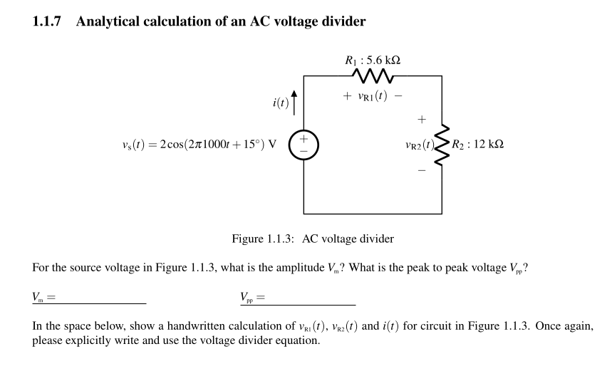
In this lesson we'll learn to quickly and directly solve for voltage across elements in series using the AC voltage divider rule without having to solve for
AC Voltage Divider. The two impedance voltage divider is used often to supply a voltage different from that of an available AC signal source. In application the output voltage depends upon the impedance of the load it drives. Note: To avoid dealing with so many short circuits, divider resistors with value zero will default to 1 when the
Voltage Divider Rule on AC Circuit Circuit Diagram
I'm not familiar of AC circuits as compared to DC circuits. But someone mentioned to me that I can use the Voltage Divider Rule (VDR) on AC circuits to drop a 240 Vac to 24 Vac by using a high watt 1 ohm resistor and a 9 ohm resistor. (240*1) / (9+1) = 24 Vac. I was thinking about it and it kind of make sense. Unlike resistive voltage divider circuits which operate on both AC and DC supplies, voltage division using capacitors is only possible with a sinusoidal AC supply. This is because the voltage division between series connected capacitors is calculated using the reactance of the capacitors, X C which is dependent on the frequency of the AC supply. You'd need to be using 0.1% resistors, or a film hybrid and laser-trim it. Furthermore, with any such divider, if it is to work on transmission lines (i.e. signal transmission circuits with controlled impedance), then it must terminate the input line with a suitable impedance, and must provide and output impedance suitable for the load.
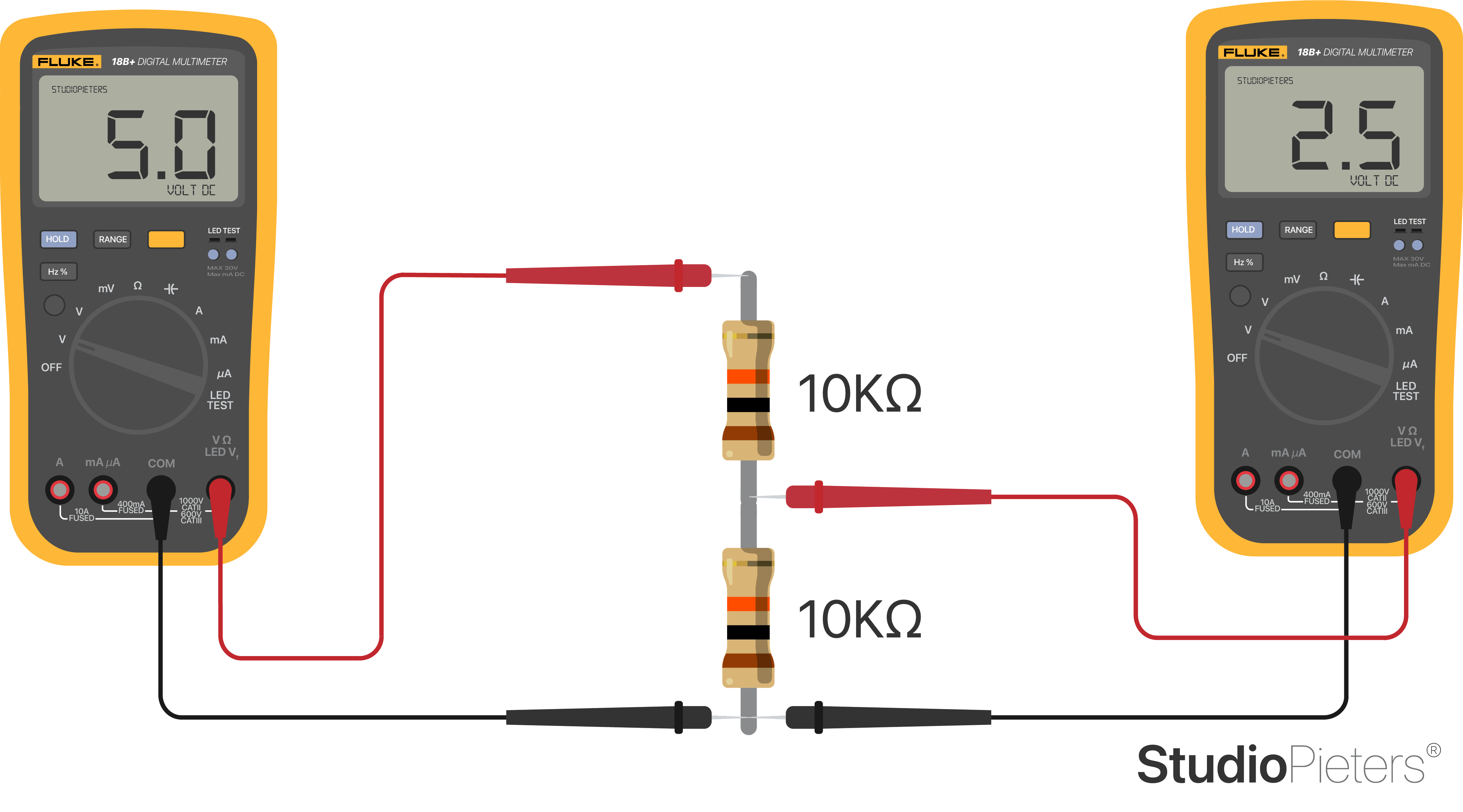
Key learnings: Voltage Divider Definition: A voltage divider is a simple circuit that creates a part of its input voltage as output, using two resistors in series.; Circuit Components: The circuit includes two resistors connected in series with a voltage source, splitting the input voltage.; Unloaded Equation: With no current flowing out, the output voltage depends on the ratio of the resistors. According to the voltage divider rule, the voltage drop across each resistor in a series circuit is directly proportional to its resistance relative to the total resistance of the circuit. In AC circuits, the application of the voltage divider rule becomes more complex due to the presence of reactive components, such as capacitors and inductors.
